/* ----------------------------------------------------------------------------
* ATMEL Microcontroller Software Support
* ----------------------------------------------------------------------------
* Copyright (c) 2008, Atmel Corporation
*
* All rights reserved.
*
* Redistribution and use in source and binary forms, with or without
* modification, are permitted provided that the following conditions are met:
*
* - Redistributions of source code must retain the above copyright notice,
* this list of conditions and the disclaimer below.
*
* Atmel's name may not be used to endorse or promote products derived from
* this software without specific prior written permission.
*
* DISCLAIMER: THIS SOFTWARE IS PROVIDED BY ATMEL "AS IS" AND ANY EXPRESS OR
* IMPLIED WARRANTIES, INCLUDING, BUT NOT LIMITED TO, THE IMPLIED WARRANTIES OF
* MERCHANTABILITY, FITNESS FOR A PARTICULAR PURPOSE AND NON-INFRINGEMENT ARE
* DISCLAIMED. IN NO EVENT SHALL ATMEL BE LIABLE FOR ANY DIRECT, INDIRECT,
* INCIDENTAL, SPECIAL, EXEMPLARY, OR CONSEQUENTIAL DAMAGES (INCLUDING, BUT NOT
* LIMITED TO, PROCUREMENT OF SUBSTITUTE GOODS OR SERVICES; LOSS OF USE, DATA,
* OR PROFITS; OR BUSINESS INTERRUPTION) HOWEVER CAUSED AND ON ANY THEORY OF
* LIABILITY, WHETHER IN CONTRACT, STRICT LIABILITY, OR TORT (INCLUDING
* NEGLIGENCE OR OTHERWISE) ARISING IN ANY WAY OUT OF THE USE OF THIS SOFTWARE,
* EVEN IF ADVISED OF THE POSSIBILITY OF SUCH DAMAGE.
* ----------------------------------------------------------------------------
*/
//------------------------------------------------------------------------------
/// \dir
/// !!!Purpose
///
/// This directory provides a library of highly re-usable code to build
/// USB applications with Atmel AT91 microcontrollers.
///
/// !!!Contents
/// The directory can basically be divided into three sections for their usage:
/// - common: %common USB definitions and routines, including standard USB
/// spec. and the following classes: audio, cdc, hid, massstorage;
/// - device: re-usable & portable software USB %device modules, including
/// general UDP driver for AT91 microcontroller and the following
/// devices: audio-speaker, ccid, cdc-serial, hid-keyboard,
/// massstorage;
/// - host: re-usable & portable software USB host modules
///
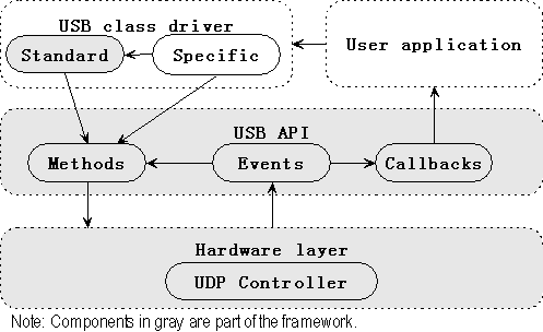
/// !!!AT91 USB device framework
/// "AT91 USB device framework" is architectured as following:
/// - #Hardware layer#: low-level operations on the USB UDP controller
/// - device/core, suffixed with UDP, UDPHS, OTGHS
/// - #USB %device API#: offers hardware-independent methods and structures
/// - device/core, other files: driver, events and callbacks
/// - common/core: general USB descriptors and requests
/// - common/, other directories: general USB class descriptors and requests
/// - #Applicatioin layer#: the USB class driver and user/demo applicaiton
/// - device/, other directories, named with the class driver function
/// - project directory, with main.c
///
/// "USB Device Framework Architecture"
/// \image USBFrameworkArchitecture.png "USB Framework Architecture"
///
/// ---
///
/// For more information about what a particular group contains, please refer to
/// its documentation page.
///
/// \note
/// Depending on the project, not all the subdirectories will be available
/// (i.e. the #host# directory will not be in projects without USB host).
//------------------------------------------------------------------------------
/**
\page "AT91 USB device framework"
AT91 USB %device framework is a device-side USB framework. It enables rapid
development of USB-compliant class drivers such as the Mass Storage Device
(MSD) or the Communication Device Class (CDC) and etc.
This page shows the index to describe the AT91 USB %device framework.
- USBD: USB Device
-# "USB Device Framework Architecture"
-# "USB Device Framework Description"
-# "Standard USB Structures"
-# "USBD API"
-# "USBD Callback API"
-# "USBD Standard Request Handler"
-# "USB Device Framework Usage"
-# "USBD File Architecture"
-# "USBD Headers"
-# "Building the Framework"
-# "USB Device Enumeration"
*/
/**
\page "USB Device Framework Architecture"
!!!Framework Architecture
The following three-tiered structure is used:
- A #hardware layer# which performs low-level operations on the USB controller.
- The #USB API# offers hardware-independent methods and structures.
- The #application layer#, made up of a USB class driver and the user
application.
The framework includes the USBD API and the hardware layer as well as a standard
request handler. The application layer is build on top of that to provide the
%device functionalty.
There are also callbacks automatically called by the USBD API to perform
specific operations, to perform communication between the USBD API and the
application layer.
\image USBFrameworkArchitecture.png "USB Framework Architecture"
*/
/* (Image Link Backup)
 */
/**
\page "USB Device Framework Description"
!!!Framework Discription
The framework is comprised of serveral components:
-# "Standard USB Structures"
-# "USBD API"
- Structures
- Methods
-# "USBD Callback API"
-# "USBD Standard Request Handler"
*/
/**
\page "USB Device Framework Usage"
!!!File Architecture
The USB framework is made up of the following files:
at91lib\\boards: %device register definition, board-related code and
%device startup code in assembly language\n
at91lib\\utility: debug methods and definitions\n
at91lib\\peripherals\\dbgu: DBGU port usage for debug\n
at91lib\\peripherals\\pio: PIO interface usage for Vbus ...\n
at91lib\\peripherals\\aic: Interrupt configurationi functions\n
at91lib\\usb\\common\\core: structures and methods of standard descriptors
and requests\n
at91lib\\usb\\device\\core: UDP controller driver methods and USBD API
definitions\n
usb-device-core-project: basic enumeration program, with main.c and
Makefile to build the project\n
!!!Headers
When programming your own application, most if not all the headers described
in the file architecture of the framework must be included. However, since
each header has its own dependencies, they must be included in a particular
order.
Here is the standard inclusion order:
\code
#include
#include
#include
#include
#include
#include
#include
#include
#include
\endcode
If a custom class driver has been added, then its header must probably be
linked last.
!!!Building the Framework
A Makefile is provided to make it easier to compile the framework. The }make}
program and arm-elf-gcc is necessary to use it.
Several options are available to build the framework in different ways:
- CHIP
- Target chip for which to build the program.
- Possible values: at91sam7s64, at91sam7s128, at91sam7s256, at91sam7s512,
at91sam7s321, at91sam7se32, at91sam7se256, at91sam7se512, at91sam7x128,
at91sam7x256, at91sam7s512, at91sam7xc128, at91sam7xc256, at91sam7xc512,
at91sam9260, at91sam9261, at91sam9263
- Default: at91sam7s256
- BOARD
- Board used with the chip.
- Possible values: at91sam7s-ek, at91sam7se-ek, at91sam7x-ek,
at91sam7xc-ek, at91sam7a3-ek, at91sam9260-ek, at91sam9261-ek,
at91sam9263-ek
- Default: at91sam7s-ek
*/
/**
\page "USB Device Enumeration"
This page is a step-by-step guide on how to use the USB Device framework
to produce a simple program that performs USB enumeration. In this example,
everything is put into a single file. You can look at the main.c file provided
with the framework to view the end result.
!!!Including the Necessary Headers
Prior to using the framework, several header files have to be included. Please
refer to "USB Device Framework Usage" for more information.
!!!Declaring Global Varibles
Several object instances are necessary to use the various functions and methods
of the USB framework. As following.
!!USBD Driver
The very first step is declare the USB driver which is then used by the Class
driver. The USBDDriver structure is used as a container for several variables,
which must therefore be created first.
!Endpoints
Depending on the application, a particular number of endpoints have to be
defined. For example, an MSD driver needs three endpoints whereas a CDC driver
needs four. Refer to the corresponding specification for more information
about the required number of endpoints. Since this example should only perform
the USB enumeration, it will declare only one endpoint: Control endpoint 0.
Endpoints is configrued by USBEndpointDescriptor in USBDDriverDescriptors for
the driver. The FIFO banks is automatically set to its maximum value.
!Callbacks
To replace the default callback, you should remove the default callback file
from makefile and add your own function defintion.
||callback function file||callback function
|USBDCallbacks_Initialized.o|USBDCallbacks_Initialized
|USBDCallbacks_Reset.o|USBDCallbacks_Reset
|USBDCallbacks_Suspended.o|USBDCallbacks_Suspended
|USBDCallbacks_Resumed.o|USBDCallbacks_Resumed
|- #MUST# be defined|USBDCallbacks_RequestReceived
!Driver
Depending on the chip used, there may or may not be a need to declare a low-
level driver variable.
The default driver global variable is simply called usbdDriver, and will
sufficient for this example.
\code
USBDDriver usbdDriver;
\endcode
!!Descriptors
The USB specification 2.0 defines a set of descriptors used to give
information about the %device. Depending on the USB class implemented,
different descriptors have to be used with varying values.
In this example program, only a few descriptors are required,. The %device
descriptor is always mandatory, so it will have to be defined. At least one
configuration descriptor is required, so one is implemented. The described
configuration must have at least one interface, so one more descriptor is
needed. Finally, no string descriptors are used:
!Device Descriptor
The device descriptor used by this example looks like this:
\code
/// Device descriptor.
const USBDeviceDescriptor usbDeviceDescriptor = {
sizeof(USBDeviceDescriptor),
USBGenericDescriptor_DEVICE,
USBDeviceDescriptor_USB2_00,
0, // No device class code
0, // No device subclass code
0, // No device protocol code
BOARD_USB_ENDPOINTS_MAXPACKETSIZE(0),
0x03EB, // Atmel vendor ID
0x0001, // Product ID
0x0001, // Product release 0.01
0, // No manufacturer string descriptor
0, // No product string descriptor
0, // No serial number string descriptor
1 // One possible configuration
};
\endcode
The values are nothing special here. Note that the first three fields have the
same data in them (unless using USB 1.1). It is also very common to define the
class, subclass and protocol values at the interface level.
- Note: The }vendor ID} value is provided by the USB-IF organization. The
}product ID} is vendor-specific and can be assigned any value.
!Configuration & Interface
When the configuration descriptor is requested by the host, via the
GET_DESCRIPTOR command, the device must not only transmit this descriptor but
also all the necessary interface and endpoint descriptors.
In order to do that easily, a structure must be defined for holding all the
information. This way, the data to send is contiguous, making the request
much simpler to fulfill. In the current example, the configuration descriptor
must be followed by the first interface descriptor. The following structure is
declared for that:
\code
// Configuration descriptors with one interface.
struct SimpleConfigurationDescriptors {
USBConfigurationDescriptor configuration;
USBInterfaceDescriptor interface;
};
\endcode
Now, the actual descriptors can be declared:
\code
// Configuration descriptors.
const struct SimpleConfigurationDescriptors configurationDescriptors = {
// Configuration descriptor
{
sizeof(USBConfigurationDescriptor),
USBGenericDescriptor_CONFIGURATION,
sizeof(struct SimpleConfigurationDescriptors),
0, // No interface in this configuration
1, // This is configuration #1
0, // No string descriptor for this configuration
BOARD_USB_BMATTRIBUTES,
USBConfigurationDescriptor_POWER(100)
},
// Interface descriptor
{
sizeof(USBInterfaceDescriptor),
USBGenericDescriptor_INTERFACE,
0, // This is interface #0
0, // This is setting #0 for interface
0, // Interface has no endpoint
0, // No interface class code
0, // No interface subclass code
0, // No interface protocol code
0, // No string descriptor
}
};
\endcode
Again, those are very generic values. For the interface descriptor, most of
them are zeroed. This is because this example does not implement any
functionality other than doing the USB enumeration.
!!Class Driver
The demonstration program is going to use the standard request handler
discussed in "USBD Standard Request Handler" to perform the USB enumeration.
To be able to do that, several structures must be declared.
!Descriptors List
The USBDDriver object needs a pointer to a list of descriptors. This is
necessary to be able to answer the GET_DESCRIPTOR request. A
USBDDriverDescriptors can be used to do that.
The actual descriptors list can be instantiated:
\code
// List of descriptors used by the device.
const USBDDriverDescriptors usbdDriverDescriptors = {
&usbDeviceDescriptor,
(const USBConfigurationDescriptor *) &configurationDescriptors,
#ifdef BOARD_USB_UDPHS
0, // No full-speed device qualifier descriptor
0, // No full-speed other speed configuration descriptor
&usbDeviceDescriptor,
(const USBConfigurationDescriptor *) &configurationDescriptors,
0, // No high-speed device qualifier descriptor
0, // No high-speed other speed configuration descriptor
#else
0, // No full-speed device qualifier descriptor
0, // No full-speed other speed configuration descriptor
0, // No high-speed device descriptor
0, // No high-speed configuration descriptor
0, // No high-speed device qualifier descriptor
0, // No high-speed other speed configuration descriptor
#endif
0, // No string descriptor
0 // No string descriptor
};
\endcode
The core configuration descriptor, which is actually made up of the
configuation descriptor and the first interface descriptor, has to be cast to
the USBConfigurationDescriptor type.
!!!Interrupt Service Routines
.
!!USB Controller Interrupt
The USB controller peripheral generates an interrupt when an event occurs.
Since that event must be forwarded to the USBD_IrqHandler method, an
interrupt service routine must be installed to do that.
\code
void ISR_Usb()
{
USBD_IrqHandler();
}
\endcode
Currently the default USBDCallbacks_Initialized will initialize the
interrupt service routine automatically:
\code
void USBDCallbacks_Initialized()
{
AIC_ConfigureIT(AT91C_ID_UDP, 0, USBD_IrqHandler);
AIC_EnableIT(AT91C_ID_UDP);
}
\endcode
So the only thing you should do to initialize the interrupt service is to call
USBD_Init() in main().
!!VBus PIO Interrupt
The Vbus power line can be monitored (if a PIO pin is connected to it) by the
user application to enable or disable the USB controller peripheral when the
%device is connected/disconnected. To do that, an interrupt must be programmed
when the status of Vbus changes. The ISR should call the USBD_Connect or
USBD_Disconnect function as follows:
\code
void ISR_Vbus(const Pin *pPin)
{
// Check current level on VBus
if (PIO_Get(&pinVbus)) {
USBD_Connect();
}
else {
USBD_Disconnect();
}
}
\endcode
!!!Callbacks
A typical application based on this USB framework needs to instantiate most of
the callbacks available. This section describes how to do that for a simple
enumeration program.
!!Init
When an OS is not being used, the primary function that the {Init{ callback
must perform is interrupt handler installation. The previously defined ISR
is thus configured and enabled:
\code
void USBDCallbacks_Initialized()
{
// Configure and enable the UDP interrupt
AIC_ConfigureIT(AT91C_ID_UDP, 0, USBD_IrqHandler);
AIC_EnableIT(AT91C_ID_UDP);
}
\endcode
The default callback is defined in USBDCallbacks_Initialized.c.
!!Suspend & Resume
The Suspend callback is used by the USBD API to notify the device that it
should enter low-power mode if required. The default callback is defined
in USBDCallbacks_Suspended.c.
\code
void USBDCallbacks_Suspended(void)
{
// Turn off LEDs
LED_Clear(USBD_LEDPOWER);
LED_Clear(USBD_LEDUSB);
}
\endcode
The Resume callback has to perform the reverse operation. The default callback
is defined in USBDCallbacks_Resumed.c.
\code
void USBDCallbacks_Resumed(void)
{
// Initialize LEDs
LED_Configure(USBD_LEDPOWER);
LED_Set(USBD_LEDPOWER);
LED_Configure(USBD_LEDUSB);
LED_Clear(USBD_LEDUSB);
}
\endcode
- Note: }It is not necessary to disable the USB controller logic (transceiver,
clocks, %peripheral) here. This is done directly by the USBD_IrqHandler
function prior to triggering the callback. Typically, the callback must carry
out the following operations:
- Disable the PLL
- Switch to the slow 32 KHz clock
- Turn off the clocks of used peripherals}
!!NewRequest
Since this example software should only perform the USB enumeration, the
NewRequest callback can simply forward the call to the standard request
handler method:
\code
void USBDCallbacks_RequestReceived(const USBGenericRequest *request)
{
USBDDriver_RequestHandler(&usbdDriver, request);
}
\endcode
!!!Main
The Main function of the program is used for PIO and driver (Class and USB)
initialization, software connections of the device (by using USBD_Connect),
and implementation of the product functionality.
In this case, the Main performs the first two steps. After that, since the
enumeration is done through the event handler and the device does not do
anything, it can simply enter an infinite loop:
\code
int main()
{
// If they are present, configure Vbus & Wake-up pins
PIO_InitializeInterrupts(0);
// USB initialization
USBDDriver_Initialize(&usbdDriver, &usbdDriverDescriptors, 0);
USBD_Init();
// connect if needed
VBUS_CONFIGURE();
while (USBD_GetState() < USBD_STATE_CONFIGURED);
// Main loop
while(1)
{
// Put USB class driver implementaion here
}
}
\endcode
*/
*/
/**
\page "USB Device Framework Description"
!!!Framework Discription
The framework is comprised of serveral components:
-# "Standard USB Structures"
-# "USBD API"
- Structures
- Methods
-# "USBD Callback API"
-# "USBD Standard Request Handler"
*/
/**
\page "USB Device Framework Usage"
!!!File Architecture
The USB framework is made up of the following files:
at91lib\\boards: %device register definition, board-related code and
%device startup code in assembly language\n
at91lib\\utility: debug methods and definitions\n
at91lib\\peripherals\\dbgu: DBGU port usage for debug\n
at91lib\\peripherals\\pio: PIO interface usage for Vbus ...\n
at91lib\\peripherals\\aic: Interrupt configurationi functions\n
at91lib\\usb\\common\\core: structures and methods of standard descriptors
and requests\n
at91lib\\usb\\device\\core: UDP controller driver methods and USBD API
definitions\n
usb-device-core-project: basic enumeration program, with main.c and
Makefile to build the project\n
!!!Headers
When programming your own application, most if not all the headers described
in the file architecture of the framework must be included. However, since
each header has its own dependencies, they must be included in a particular
order.
Here is the standard inclusion order:
\code
#include
#include
#include
#include
#include
#include
#include
#include
#include
\endcode
If a custom class driver has been added, then its header must probably be
linked last.
!!!Building the Framework
A Makefile is provided to make it easier to compile the framework. The }make}
program and arm-elf-gcc is necessary to use it.
Several options are available to build the framework in different ways:
- CHIP
- Target chip for which to build the program.
- Possible values: at91sam7s64, at91sam7s128, at91sam7s256, at91sam7s512,
at91sam7s321, at91sam7se32, at91sam7se256, at91sam7se512, at91sam7x128,
at91sam7x256, at91sam7s512, at91sam7xc128, at91sam7xc256, at91sam7xc512,
at91sam9260, at91sam9261, at91sam9263
- Default: at91sam7s256
- BOARD
- Board used with the chip.
- Possible values: at91sam7s-ek, at91sam7se-ek, at91sam7x-ek,
at91sam7xc-ek, at91sam7a3-ek, at91sam9260-ek, at91sam9261-ek,
at91sam9263-ek
- Default: at91sam7s-ek
*/
/**
\page "USB Device Enumeration"
This page is a step-by-step guide on how to use the USB Device framework
to produce a simple program that performs USB enumeration. In this example,
everything is put into a single file. You can look at the main.c file provided
with the framework to view the end result.
!!!Including the Necessary Headers
Prior to using the framework, several header files have to be included. Please
refer to "USB Device Framework Usage" for more information.
!!!Declaring Global Varibles
Several object instances are necessary to use the various functions and methods
of the USB framework. As following.
!!USBD Driver
The very first step is declare the USB driver which is then used by the Class
driver. The USBDDriver structure is used as a container for several variables,
which must therefore be created first.
!Endpoints
Depending on the application, a particular number of endpoints have to be
defined. For example, an MSD driver needs three endpoints whereas a CDC driver
needs four. Refer to the corresponding specification for more information
about the required number of endpoints. Since this example should only perform
the USB enumeration, it will declare only one endpoint: Control endpoint 0.
Endpoints is configrued by USBEndpointDescriptor in USBDDriverDescriptors for
the driver. The FIFO banks is automatically set to its maximum value.
!Callbacks
To replace the default callback, you should remove the default callback file
from makefile and add your own function defintion.
||callback function file||callback function
|USBDCallbacks_Initialized.o|USBDCallbacks_Initialized
|USBDCallbacks_Reset.o|USBDCallbacks_Reset
|USBDCallbacks_Suspended.o|USBDCallbacks_Suspended
|USBDCallbacks_Resumed.o|USBDCallbacks_Resumed
|- #MUST# be defined|USBDCallbacks_RequestReceived
!Driver
Depending on the chip used, there may or may not be a need to declare a low-
level driver variable.
The default driver global variable is simply called usbdDriver, and will
sufficient for this example.
\code
USBDDriver usbdDriver;
\endcode
!!Descriptors
The USB specification 2.0 defines a set of descriptors used to give
information about the %device. Depending on the USB class implemented,
different descriptors have to be used with varying values.
In this example program, only a few descriptors are required,. The %device
descriptor is always mandatory, so it will have to be defined. At least one
configuration descriptor is required, so one is implemented. The described
configuration must have at least one interface, so one more descriptor is
needed. Finally, no string descriptors are used:
!Device Descriptor
The device descriptor used by this example looks like this:
\code
/// Device descriptor.
const USBDeviceDescriptor usbDeviceDescriptor = {
sizeof(USBDeviceDescriptor),
USBGenericDescriptor_DEVICE,
USBDeviceDescriptor_USB2_00,
0, // No device class code
0, // No device subclass code
0, // No device protocol code
BOARD_USB_ENDPOINTS_MAXPACKETSIZE(0),
0x03EB, // Atmel vendor ID
0x0001, // Product ID
0x0001, // Product release 0.01
0, // No manufacturer string descriptor
0, // No product string descriptor
0, // No serial number string descriptor
1 // One possible configuration
};
\endcode
The values are nothing special here. Note that the first three fields have the
same data in them (unless using USB 1.1). It is also very common to define the
class, subclass and protocol values at the interface level.
- Note: The }vendor ID} value is provided by the USB-IF organization. The
}product ID} is vendor-specific and can be assigned any value.
!Configuration & Interface
When the configuration descriptor is requested by the host, via the
GET_DESCRIPTOR command, the device must not only transmit this descriptor but
also all the necessary interface and endpoint descriptors.
In order to do that easily, a structure must be defined for holding all the
information. This way, the data to send is contiguous, making the request
much simpler to fulfill. In the current example, the configuration descriptor
must be followed by the first interface descriptor. The following structure is
declared for that:
\code
// Configuration descriptors with one interface.
struct SimpleConfigurationDescriptors {
USBConfigurationDescriptor configuration;
USBInterfaceDescriptor interface;
};
\endcode
Now, the actual descriptors can be declared:
\code
// Configuration descriptors.
const struct SimpleConfigurationDescriptors configurationDescriptors = {
// Configuration descriptor
{
sizeof(USBConfigurationDescriptor),
USBGenericDescriptor_CONFIGURATION,
sizeof(struct SimpleConfigurationDescriptors),
0, // No interface in this configuration
1, // This is configuration #1
0, // No string descriptor for this configuration
BOARD_USB_BMATTRIBUTES,
USBConfigurationDescriptor_POWER(100)
},
// Interface descriptor
{
sizeof(USBInterfaceDescriptor),
USBGenericDescriptor_INTERFACE,
0, // This is interface #0
0, // This is setting #0 for interface
0, // Interface has no endpoint
0, // No interface class code
0, // No interface subclass code
0, // No interface protocol code
0, // No string descriptor
}
};
\endcode
Again, those are very generic values. For the interface descriptor, most of
them are zeroed. This is because this example does not implement any
functionality other than doing the USB enumeration.
!!Class Driver
The demonstration program is going to use the standard request handler
discussed in "USBD Standard Request Handler" to perform the USB enumeration.
To be able to do that, several structures must be declared.
!Descriptors List
The USBDDriver object needs a pointer to a list of descriptors. This is
necessary to be able to answer the GET_DESCRIPTOR request. A
USBDDriverDescriptors can be used to do that.
The actual descriptors list can be instantiated:
\code
// List of descriptors used by the device.
const USBDDriverDescriptors usbdDriverDescriptors = {
&usbDeviceDescriptor,
(const USBConfigurationDescriptor *) &configurationDescriptors,
#ifdef BOARD_USB_UDPHS
0, // No full-speed device qualifier descriptor
0, // No full-speed other speed configuration descriptor
&usbDeviceDescriptor,
(const USBConfigurationDescriptor *) &configurationDescriptors,
0, // No high-speed device qualifier descriptor
0, // No high-speed other speed configuration descriptor
#else
0, // No full-speed device qualifier descriptor
0, // No full-speed other speed configuration descriptor
0, // No high-speed device descriptor
0, // No high-speed configuration descriptor
0, // No high-speed device qualifier descriptor
0, // No high-speed other speed configuration descriptor
#endif
0, // No string descriptor
0 // No string descriptor
};
\endcode
The core configuration descriptor, which is actually made up of the
configuation descriptor and the first interface descriptor, has to be cast to
the USBConfigurationDescriptor type.
!!!Interrupt Service Routines
.
!!USB Controller Interrupt
The USB controller peripheral generates an interrupt when an event occurs.
Since that event must be forwarded to the USBD_IrqHandler method, an
interrupt service routine must be installed to do that.
\code
void ISR_Usb()
{
USBD_IrqHandler();
}
\endcode
Currently the default USBDCallbacks_Initialized will initialize the
interrupt service routine automatically:
\code
void USBDCallbacks_Initialized()
{
AIC_ConfigureIT(AT91C_ID_UDP, 0, USBD_IrqHandler);
AIC_EnableIT(AT91C_ID_UDP);
}
\endcode
So the only thing you should do to initialize the interrupt service is to call
USBD_Init() in main().
!!VBus PIO Interrupt
The Vbus power line can be monitored (if a PIO pin is connected to it) by the
user application to enable or disable the USB controller peripheral when the
%device is connected/disconnected. To do that, an interrupt must be programmed
when the status of Vbus changes. The ISR should call the USBD_Connect or
USBD_Disconnect function as follows:
\code
void ISR_Vbus(const Pin *pPin)
{
// Check current level on VBus
if (PIO_Get(&pinVbus)) {
USBD_Connect();
}
else {
USBD_Disconnect();
}
}
\endcode
!!!Callbacks
A typical application based on this USB framework needs to instantiate most of
the callbacks available. This section describes how to do that for a simple
enumeration program.
!!Init
When an OS is not being used, the primary function that the {Init{ callback
must perform is interrupt handler installation. The previously defined ISR
is thus configured and enabled:
\code
void USBDCallbacks_Initialized()
{
// Configure and enable the UDP interrupt
AIC_ConfigureIT(AT91C_ID_UDP, 0, USBD_IrqHandler);
AIC_EnableIT(AT91C_ID_UDP);
}
\endcode
The default callback is defined in USBDCallbacks_Initialized.c.
!!Suspend & Resume
The Suspend callback is used by the USBD API to notify the device that it
should enter low-power mode if required. The default callback is defined
in USBDCallbacks_Suspended.c.
\code
void USBDCallbacks_Suspended(void)
{
// Turn off LEDs
LED_Clear(USBD_LEDPOWER);
LED_Clear(USBD_LEDUSB);
}
\endcode
The Resume callback has to perform the reverse operation. The default callback
is defined in USBDCallbacks_Resumed.c.
\code
void USBDCallbacks_Resumed(void)
{
// Initialize LEDs
LED_Configure(USBD_LEDPOWER);
LED_Set(USBD_LEDPOWER);
LED_Configure(USBD_LEDUSB);
LED_Clear(USBD_LEDUSB);
}
\endcode
- Note: }It is not necessary to disable the USB controller logic (transceiver,
clocks, %peripheral) here. This is done directly by the USBD_IrqHandler
function prior to triggering the callback. Typically, the callback must carry
out the following operations:
- Disable the PLL
- Switch to the slow 32 KHz clock
- Turn off the clocks of used peripherals}
!!NewRequest
Since this example software should only perform the USB enumeration, the
NewRequest callback can simply forward the call to the standard request
handler method:
\code
void USBDCallbacks_RequestReceived(const USBGenericRequest *request)
{
USBDDriver_RequestHandler(&usbdDriver, request);
}
\endcode
!!!Main
The Main function of the program is used for PIO and driver (Class and USB)
initialization, software connections of the device (by using USBD_Connect),
and implementation of the product functionality.
In this case, the Main performs the first two steps. After that, since the
enumeration is done through the event handler and the device does not do
anything, it can simply enter an infinite loop:
\code
int main()
{
// If they are present, configure Vbus & Wake-up pins
PIO_InitializeInterrupts(0);
// USB initialization
USBDDriver_Initialize(&usbdDriver, &usbdDriverDescriptors, 0);
USBD_Init();
// connect if needed
VBUS_CONFIGURE();
while (USBD_GetState() < USBD_STATE_CONFIGURED);
// Main loop
while(1)
{
// Put USB class driver implementaion here
}
}
\endcode
*/