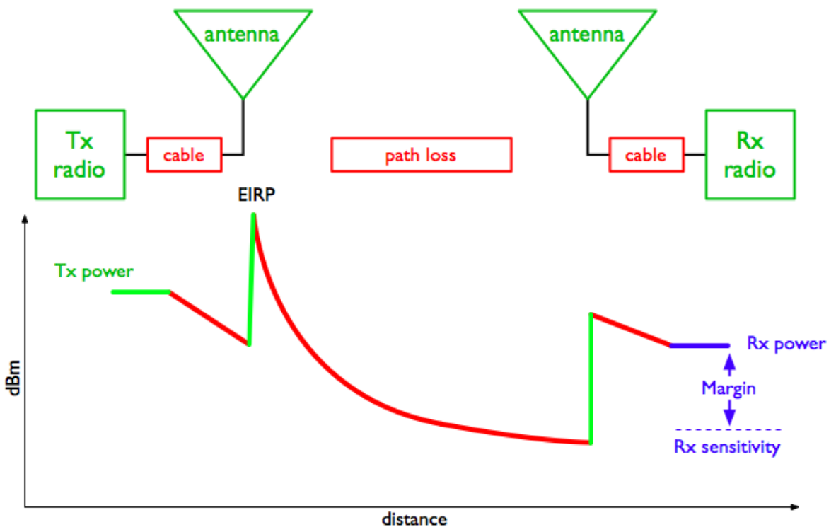
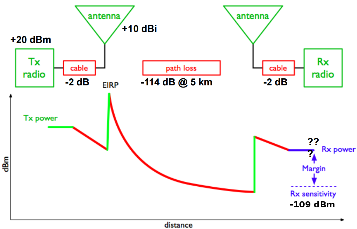
RF Power in a Wireless Link

The transmit power of a MS depends on various factors, such as the MS Power Class, the frequency band and the modulation scheme used.
| Power Class | Band | Modulation | Power |
|---|---|---|---|
4 |
850 / 900 |
GMSK |
33 dBm (2 W) |
1 |
1800 / 1900 |
GMSK |
30 dBm (1 W) |
E2 |
850 / 900 |
8PSK |
27 dBm (0.5 W) |
E2 |
1800 / 1900 |
8PSK |
26 dBm (0.4 W) |
The minimum reference sensitivity level of a normal GSM BTS is specified in 3GPP TS 05.05 and required to be at least -104 dBm. Most modern BTSs outperform this significantly.
FIXME: Example calculation (spreadsheet screenshot?)

The transmit power of the BTS depends on your BTS model and any possible external power amplifiers used.
The minimum reference sensitivity level of a GSM MS is specified in 3GPP TS 05.05 and can typically be assumed to be about -102 dB.
FIXME: Example calculation (spreadsheet screenshot?)
Setup and Operation of a GSM network is not only about the configuration and system administration on the network elements and protocol stack, but also includes the physical radio transmission part.
Basic understanding about RF (Radio Frequency) Electronics is key to achieving good performance of the GSM network.
Coaxial cables come in many different shapes, diameters, physical construction, dielectric materials, and last but not least brands and types.
There are many parameters that might be relevant to your particular installation, starting from mechanical/environmental properties such as temperature range, UV resilience, water/weatherproofness, flammability, etc.
For the subject of this manual, we will not look at those mechanical properties, but look at the electrical properties instead.
The prime electrical parameters of a coaxial cable are:
The attenuation of a coaxial cable is given in dB per length, commonly in dB per 100m. This value changes significantly depending on the frequency of the signal transmitted via the cable. Cable manufacturers typically either provide tables with discrete frequency values, or graphs plotting the attenuation per 100m (x axis) over the frequency (y axis).
FIXME: Example.
So in order to estimate the loss of a coaxial cable, you need to
A real cable always has connectors attached to it, please add some additional losses for the connectors that are attached. 0.05 dB per connector is a general rule of thumb for the frequencies used in GSM.
FIXME: Example computation
As you can see very easily, the losses incurred in coaxial cables between your antenna and the BTS can very quickly become significant factors in your overall link budget (and thus cell coverage). This is particularly relevant for the uplink power budget. Every dB you loose in the antenna cable between antenna and the BTS receiver translates into reduced uplink coverage.
Using the shortest possible coaxial cabling (e.g. by mounting the BTS high up on the antenna tower) and using the highest-quality cabling are the best strategies to optimize
|
Warning
|
If you plan to assemble the coaxial connectors yourself, please make sure you ensure to have the right skills for this. Properly assembling coaxial connectors (whether solder-type or crimp-type) requires precision tools and strict process as described by the manufacturer. Any mechanical imprecision of connector assembly will cause significant extra signal attenuation. |
If you would like to check the proper operation of a coaxial cable, there are several possible methods available:
A coaxial connector is a connector specifically designed for mounting to coaxial cable. It facilitates the removable / detachable connection of a coaxial cable to a RF device.
There are many different types of coaxial connectors on the market.
The most important types of coaxial connectors in the context of GSM BTSs are:
FIXME: Images
The above connectors are tightened by a screw-on shell. Each connector type has a specific designated nominal torque by which the connector shall be tightened. In case of uncertainty, please ask your connector supplier for the nominal torque.
|
Note
|
Always ensure the proper mechanical condition of your RF connectors. Don’t use RF connectors that are contaminated by dust or dirt, or which show significant oxidization, bent contacts or the like. Using such connectors poses significant danger of unwanted signal loss, and can in some cases even lead to equipment damage (e.g. in case of RF power at PA output being reflected back into the PA). |
A GSM BTS (or GSM TRX inside a BTS) typically exposes separate ports for Rx (Receive) and Tx (Transmit). This is intentionally the case, as this allows the users to add e.g. additional power amplifiers, filters or other external components into the signal path. Those components typically operate on either the receive or the transmit path.
You could now connect two separate antennas to the two ports (one for Rx, one for Tx). This is commonly done in indoor installations with small rubber-type antennas directly attached to the BTS connectors.
In outdoor installations, you typically (want to) use a single Antenna for Rx and Tx. This single antenna needs to be connected to the BTS via a device that is called Duplexer.
The Duplexer is actually a frequency splitter/combiner, which is specifically tuned to the uplink and downlink frequencies of the GSM band in which you operate the BTS. As such, it has one port that passes only uplink frequencies between the antenna and that port, as well as another port that passes only downlink frequencies between antenna and that port.

|
Warning
|
The ports of a duplexer are not interchangeable. Always make sure that you use the Rx port of the duplexer with the Rx port of the BTS, and vice-versa for Tx. |
A RF Power Amplifier (PA) is a device that boosts the transmit power of your RF signal, the BTS in your case.
RF power amplifiers come in many different characteristics. Some of the key characteristics are:
A PA is typically designed for a specific frequency range. Only signals inside that range will be properly amplified
This tells you how many dB the power amplifier will increase your
signal. Pout = Pin + Gain
This indicates the maximum absolute output power. For example, if the maximum output power is 40 dBm, and the gain is 10dBm, then an input signal of 30dBm will render the maximum output power. An input signal of 20dBm would subsequently generate only 30dBm of output power.
The efficiency determines how much electrical power is consumed for the given output power. Often expressed as Power Added Efficiency (PAE).
|
Warning
|
If you add external power amplifiers to a GSM BTS or any other transmitter, this will invalidate the regulatory approval of the BTS. It is your responsibility to ensure that the combination of BTS and PA still fulfills all regulatory requirements, for example in terms of out-of-band emissions, spectrum envelope, phase error, linearity, etc! |

The Antenna is responsible for converting the electromagnetic waves between the coaxial cable and the so-called air interface and vice-versa. The properties of an antenna are always symmetric for both transmission and reception.
Antennas come in many different types and shapes. Key characteristics distinguishing antennas are:
Expresses how much more efficient the antenna converts between cable and air interface. Can be expressed in dB compared to a theoretical isotropic radiator (dBi) or compared to a dipole antenna (dBd). Gain usually implies directivity.
Antennas typically have only a relatively narrow band (or multiple narrow bands at which they radiate efficiently. In general, the higher the antenna gain, the lower the usable frequency band of the antenna.
Antennas radiate the energy in all three dimensions.
Mechanical Size is an important factor depending on how and where the antenna is mounted. Size also relates to weight and wind-load.
Expresses how much mechanical load the antenna will put on its support structure (antenna mast).
Your cabling will have to use a compatible connector for the antenna. Outdoor antennas typically use the 7/16 type connector or an N type connector. Indoor antennas either N type or SMA type.
Indoor antennas cannot be used outdoor, as they do not offer the level of protection against dust and particularly water / humidity / corrosion.
Particularly sector antennas are typically installed with a fixed or (mechanically / electrically) variable down-tilt in order to limit the radius/horizon of the antenna footprint and avoid excess interference with surrounding cells.
The Voltage Standing Wave Ratio indicates how well the antenna is matched to the coaxial cable, and how much of the to-be-transmitted radio signal is actually converted to radio waves versus reflected back on the RF cable towards the transmitter. An ideal antenna has a VSWR of 1 (sometimes written 1:1). Real antennas are typically in the range of 1.2 to 2.
A directional antenna never radiates only in one direction but always has certain side lobes pointing outside of the main direction of the antenna. The number and strength of side lobes differ from antenna to antenna model.
|
Note
|
Whenever installing antennas it is important to understand that any metallic or otherwise conductive object in their vicinity will inevitably alter the antenna performance. This can affect the radiation pattern, but also de-tune the antenna and shift its frequency band outside the nominal usable frequency band. It is thus best to mount antennas as far as practically possible from conductive elements within their radiation pattern |
Omni-directional antennas are typically thin long dipole antennas covered with fiberglass. They radiate with equal strength in all directions and thus result in a more or less circular cell footprint (assuming flat terrain). The shape of the radiation pattern is a torus (donut) with the antenna located in the center of that torus.
Omni-directional antennas come with a variety of gains, typically from 0 dBd to 3 dBd, 6 dBd and sometimes 9 dBd. This gain is achieved by compressing the radiation torus in the vertical plane.
Sometimes, Omni-directional antennas can be obtained with a fixed down-tilt to limit the cell radius.
Sector antennas are used in sectorized cell setups. Sector antennas can have significantly higher gain than omni-directional antennas.
Instead of mounting a single BTS with an omni-directional antenna to a given antenna pole, multiple BTSs with each one sector antenna are mounted to the same pole. This results in an overall larger radius due to the higher gain of the sector antennas, and also in an overall capacity increase, as each sector has the same capacity as a single omni-directional cell. And all that benefit still requires only a single physical site with antenna pole, power supply, back-haul cabling, etc.
Experimentation and simulation has shown that typically the use of three sectors with antennas of an opening angle of 65 degrees results in the most optimal combination for GSM networks. If more sectors are being deployed, there is a lot of overlap between the sectors, and the amount of hand-overs between the BTSs is increased.
A RF Low Noise Amplifier (LNA) is a device that amplifies the weak received signal. In general, LNAs are combined with band filters, to ensure that only those frequencies within the receive band are amplified, and out-of-band interferers are filtered out. A duplexer can already be a sufficient band-filter, depending on its characteristics.
The use of a LNA typically only makes sense if you . have very long and/or lossy coaxial cables from your antenna to the BTS, and . can mount the duplexer + LNA close to the antenna, so that the amplification happens before the long/lossy coaxial line to the BTS
Key characteristics of a LNA are:
A LNA is typically designed for a specific frequency range. Only signals inside that range will be properly amplified
This tells you how many dB the low noise amplifier will increase your
signal. Pout = Pin + Gain
This indicates the maximum RF power at the PA input before saturation.
This indicates how much noise this LNA will add to the signal. This noise will add to the interference as seen by the receiver.


As any LNA will add noise to the signal, it is generally discouraged to add them to the system. Instead, we recommend you to mount the entire BTS closer to the antenna, thereby removing the losses created by lengthy coaxial wire. The power supply lines and Ethernet connection to the BTS are far less critical when it comes to cable length.